High-Precision GNSS Technology Empowers UAV Flight Control Systems
High-precision GNSS technology unlocks centimeter-level positioning and real-time heading calculation capabilities for UAV flight control by integrating professional-grade receivers with open-source flight control systems. This solution provides stable and reliable spatiotemporal reference, significantly enhances navigation robustness in complex environments, supports multi-source data fusion for position, velocity, and attitude, and follows a modular design philosophy balancing plug-and-play convenience with deep customization.
ArduPilot Overview
ArduPilot is a leading open-source autopilot system providing core autonomous flight and driving control for various unmanned vehicles including multicopters, fixed-wing aircraft, ground vehicles, underwater robots, and antenna trackers. It consists of open-source firmware, a rich hardware ecosystem, powerful ground control station (GCS) software, and a global community.
Core Components
- Hardware Platform: Supports a wide range from APM and Pixhawk series to Linux-based boards like Raspberry Pi
- Firmware: Core software divided by vehicle type — ArduCopter, ArduPlane, ArduRover, ArduSub, AntennaTracker
- Ground Control Station (GCS): Mission Planner (Windows), QGroundControl, MAVProxy for setup, mission planning, telemetry, and log analysis
- Community & Support: Active global community with forums, Wiki, and Commercial Partner program
Core Features & Advantages
- Mature & Reliable: Over 15 years of development, proven in countless real-world applications including winning international drone challenges and polar flights
- Open Source: All development public on GitHub, promoting rapid innovation and transparent collaboration
- Advanced Features: Swarm coordination, visual obstacle avoidance, precision landing, dynamic positioning, and EKF-based sensor fusion
- Highly Customizable: Hardware Abstraction Layer (HAL) design allows easy adaptation to new hardware
- Complete Toolchain: HITL simulation, automated testing, and log analysis tools
Getting Started
Standard process: choose hardware, install and configure, test and tune in a safe environment, then execute missions. Users should carefully follow the official “First Time Setup” and “First Flight” guides for safe operation.
Step Guide: Integrating Septentrio GNSS Receiver with ArduPilot on Pixhawk
This guide uses the Pixhawk 4 flight controller with an AsteRx-m3 Pro+ receiver on a RIB board, but is compatible with all Pixhawk-standard flight controllers.
Materials Required
- Windows laptop/desktop PC
- AsteRx GNSS OEM receiver
- RIB board (Note: Only COM2 outputs voltage levels suitable for the autopilot)
- Pixhawk 4 flight controller flashed with latest ArduPilot firmware
- CBL_UAS_44-pin to Autopilot cable (Septentrio Part No. 215947)
- Latest Mission Planner GCS software
- Dual-frequency GNSS antenna(s) (one or two)
- Adapters and cables for MMCX interfaces
- 2 Micro-USB cables
Hardware Setup
- Ensure the receiver is powered with at least 3.3V via Micro-USB or the open-ended supply (labeled “PWR & GND”) on the 44-pin cable
- Connect one or two GNSS antennas to the external antenna ports on the AsteRx-m3 Pro+ board
- Connect the 44-pin cable to the RIB board’s 44-pin connector
- Connect the 6-pin JST GH connector to the UART & I2C B port on the Pixhawk 4
Software Configuration
- Download and install Mission Planner on a Windows laptop. Connect Pixhawk 4 via Micro-USB
- Install official ArduPilot firmware via Setup tab (select firmware for your vehicle type). For GNSS attitude support, download custom firmware from the Septentrio GitHub release page
- In Mission Planner, select the correct port for Pixhawk 4 and click Connect
- Go to CONFIG tab > Full Parameter List, find GPS sub-section
- Set GPS_TYPE2 = 10 to select SBF as the incoming data format
- Set SERIAL4_BAUD = 115 and SERIAL4_PROTOCOL = 5 (GPS)
- Optionally set GPS_AUTO_CONFIG = 1 for automatic configuration, or keep it off for manual setup
- Click “Write Params” to save settings
Receiver Configuration
- Open the receiver’s webUI and define an SBF data stream on COM2 with 10 Hz output rate
- Required SBF messages: PVTGeodetic, DOP, VelCovGeodetic, BaseVectorGeod, ReceiverStatus
- Save current configuration to non-volatile memory: Admin > Configurations > copy “Current” to “Boot”
Verification
On the Flight Data screen, GPS2 status should display “3D Fix” with a location indicator on the map, confirming the Pixhawk is receiving SBF data through the receiver’s COM2 serial port.
Dual-Antenna Heading Configuration
To use both GNSS position and heading, output AuxAntPositions and AttCovEuler SBF messages through COM2, and modify these ArduPilot parameters:
- AHRS_EKF_TYPE = 3 (to use EKF3)
- EK2_ENABLE = 0 (disable EKF2)
- EK3_ENABLE = 1 (enable EKF3)
- EK3_SRC1_YAW = 2 (“GPS”) or 3 (“GPS with Compass Fallback”)
- GPS_TYPE2 = 26 (SBF-Heading)
- GPS_MB1_OFS_X, GPS_MB1_OFS_Y, GPS_MB1_OFS_Z — set according to your application
Click “Write Params” to save. Both position and heading should now display in Mission Planner.
Related GNSS Products
- HB21 GNSS Box Receiver — All-in-one RTK receiver with integrated 4G LTE, heading, and data logging
- HB6 GNSS Box Receiver — Compact quad-constellation RTK receiver powered by Septentrio Mosaic X5
- EV322 GNSS Receiver — Lightweight RTK receiver for UAVs and autonomous systems
- AIM+ Anti-Jamming Technology — Advanced interference and spoofing protection
Browse our full GNSS receiver collection for professional UAV applications.
Frequently Asked Questions
Which Septentrio receivers are compatible with Pixhawk and ArduPilot?
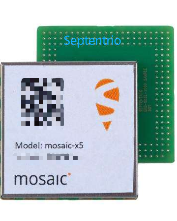
The AsteRx-m3 Pro+ and mosaic-X5 are the most commonly integrated receivers. Both support SBF output over UART and are directly compatible with Pixhawk-series flight controllers running ArduPilot. The AsteRx-m3 Pro+ provides heading via dual antennas, while the mosaic-X5 offers a more compact form factor for space-constrained platforms.
What SBF messages are required for basic ArduPilot integration?
For single-antenna operation, configure a 10 Hz SBF stream with: PVTGeodetic (position, velocity, time), DOP (dilution of precision), VelCovGeodetic (velocity covariance), BaseVectorGeod (baseline vector), and ReceiverStatus (receiver status). For dual-antenna heading, additionally output AuxAntPositions and AttCovEuler.
Why must the COM2 port be used on the RIB board?
Only COM2 on the RIB board outputs voltage levels compatible with the Pixhawk flight controller’s serial port input. Using other ports may cause signal mismatch, communication failures, or hardware damage. Always use the dedicated CBL_UAS_44-pin cable (Part No. 215947) for the connection.
How do I persist the GNSS receiver configuration after power cycling?
The receiver’s runtime configuration is stored in volatile memory. Use the web interface: Admin > Configurations, then copy the “Current” configuration to “Boot” (start-up). This saves all settings including SBF data stream output to non-volatile memory so they persist after power loss.