Can a drone survey be more accurate than its base station? No. Every RTK position the aircraft logs is a correction applied against the base’s own coordinate, so the base station sets the accuracy ceiling for the flight — and, more importantly, decides whether this week’s map lines up with last month’s.
Short version: put a receiver that is licensed for RTK Base output on a rigid mount under open sky, give the antenna a known calibration, and fix the base coordinate from a survey marker, a PPP solution or an averaged RTK fix. Leave it on auto and the flight data will look perfect while being impossible to compare with any other flight. Send RTCMv3 MSM4 at 1 Hz to the autopilot and save the configuration to boot.
What follows is the ground half of a drone RTK workflow, based on Septentrio’s six-chapter technical note How to set up a base station and its worked example with a PolaRx5e receiver and VeraPhase 6000 antenna. Figures are reproduced from that document.
The drone is rarely the weak link
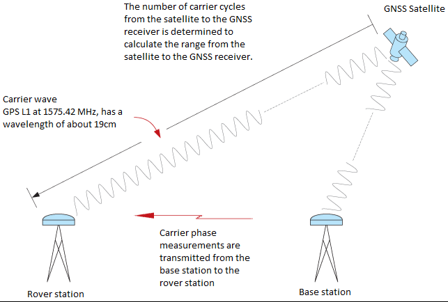
A modern multi-constellation receiver on the airframe will happily report centimetre-level RTK. The question that decides whether the deliverable is usable is different: centimetres relative to what? RTK resolves the aircraft’s position against the base’s reference coordinate using carrier-phase measurements and differential corrections. If the reference coordinate is wrong, every point on the map is shifted by the same amount — consistently, invisibly, and confidently.
Baseline length is the second lever. Because differential corrections assume both receivers sample broadly the same atmosphere, accuracy degrades as the aircraft flies away from the base. On a drone job the baseline is usually easy to keep short — the base sits at the launch point and the aircraft works a few hundred metres to a couple of kilometres away — but regional ionospheric activity sets how much stretch is acceptable, and a large site is better served by two or three base positions than by one long radio link.
Ground kit: receiver, antenna, mount
Anything from a dedicated reference receiver to an OEM module can serve as a base once integrated. For drone crews the practical shortlist is a compact receiver with a serial or Ethernet correction output and, ideally, raw logging on board — the same log that feeds RTK today becomes the PPK dataset tomorrow if the radio link misbehaves mid-flight.
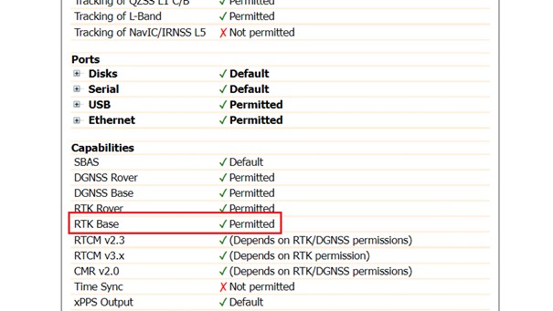
Two receiver properties are non-negotiable. First, correction output — called RTK Base in Septentrio’s interface — is a licensed capability, so confirm it is enabled on the unit you intend to leave on the ground.
Second, the receiver has to track the signals your aircraft uses. Write down the constellations and frequencies the autopilot and the payload GNSS actually consume, then confirm the base can produce corrections for them. More supported signals means more chances of a solid fixed solution rather than a float one.
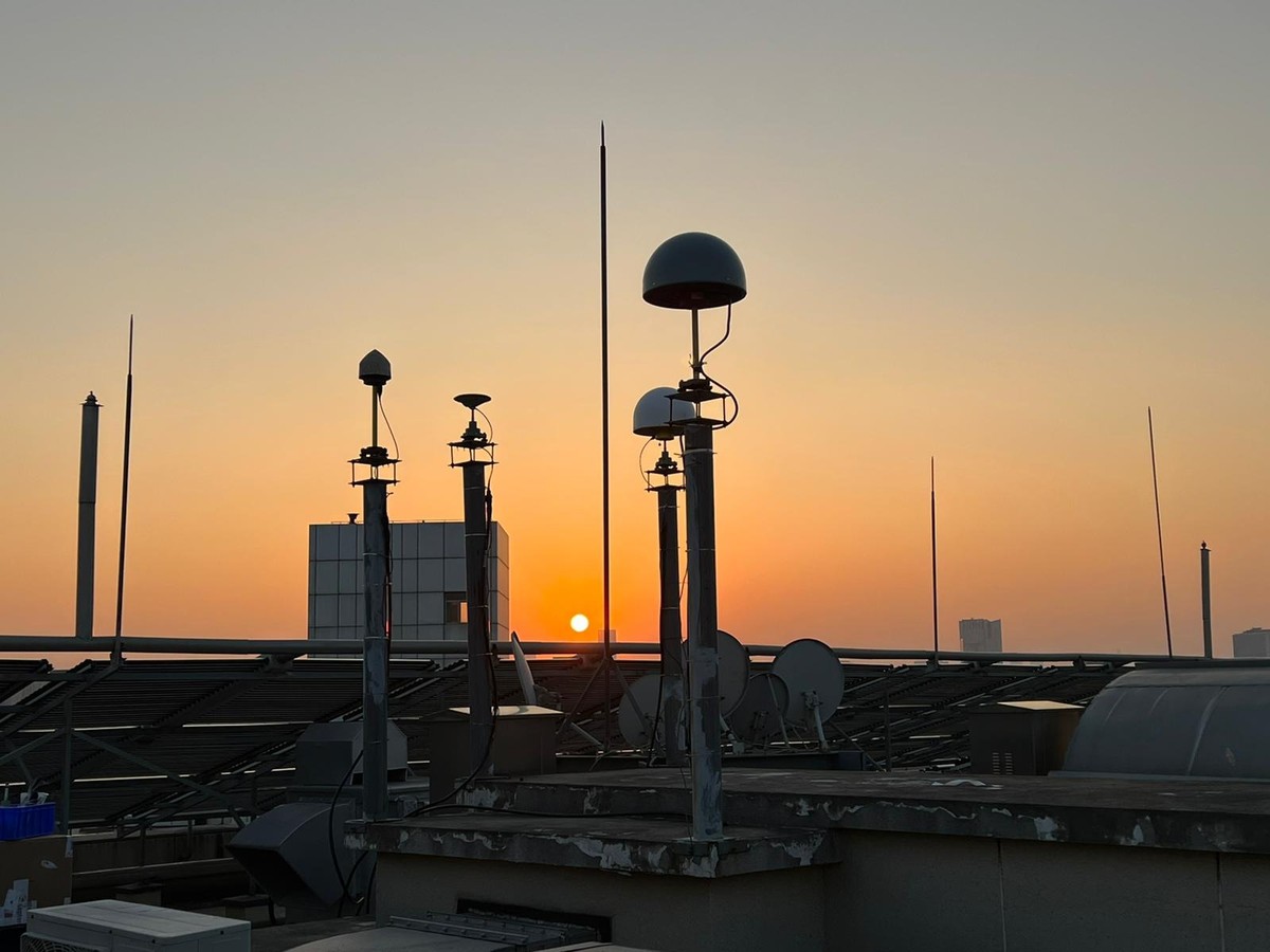
On the antenna side, three questions: how big and heavy is it, will the installation be permanent or packed into a case each morning, and does that exact model have a relative or absolute calibration on file. Choke-ring antennas are the strongest performers for static work — best multipath rejection and normally sold with an absolute calibration — which is why permanent monitoring sites use them. A geodetic antenna such as the PolaNt-x MF is usually more than adequate for a temporary flight base, and a receiver with an integrated antenna is a legitimate option when the base moves every day.
Whatever the mount — tripod, magnetic pole, welded bracket, concrete pillar — rigidity decides how often the base coordinate has to be redone. A tripod nudged by a vehicle between flights silently changes the reference for everything that follows.
Where to put the antenna on a survey site
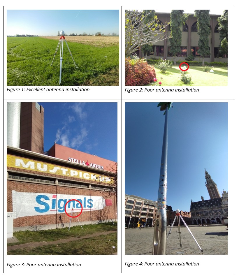
Open sky, unobstructed, and away from anything that reflects or radiates. On a drone job the usual offenders are on site rather than on the horizon: the tailgate of the survey vehicle, a metal fence or container wall, the generator, and the crew’s own radios. An antenna with a clear view and no nearby reflector is worth more than a better receiver.
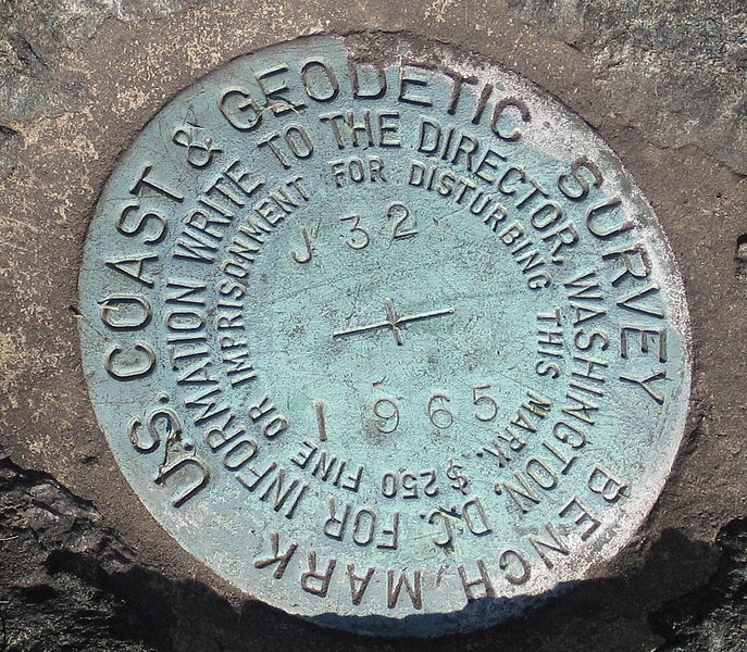
Keep the antenna vertical and take the cable strain off the connector; the connector should not be hanging on the cable’s weight. Permanent or semi-permanent sites want a surge arrester. Runs beyond roughly 20 metres call for low-loss cable, and wet or marine environments need protection at the joints — cold-shrink sleeving is the usual answer. If the reference position will come from a marker, the antenna goes exactly over it and the height offset is measured and entered, not estimated.
Fixing the reference position: four options, three of them defensible
This is where most drone RTK problems originate, and it has nothing to do with the aircraft. There are four ways to give the base a coordinate.
Known marker under the antenna
If the site has a geodetic control point or survey marker, use it. Set the antenna over the marker with a tribrach and tripod, confirm the published coordinates are both accurate and current, and enter them as the geodetic or Cartesian reference position. Then compensate the height from the marker to the antenna reference point by entering the marker-to-ARP offset and choosing the right antenna type — omit that and the phase-centre error is distributed over every corrected position in the flight.
Post-processed PPP, submitted after the flight
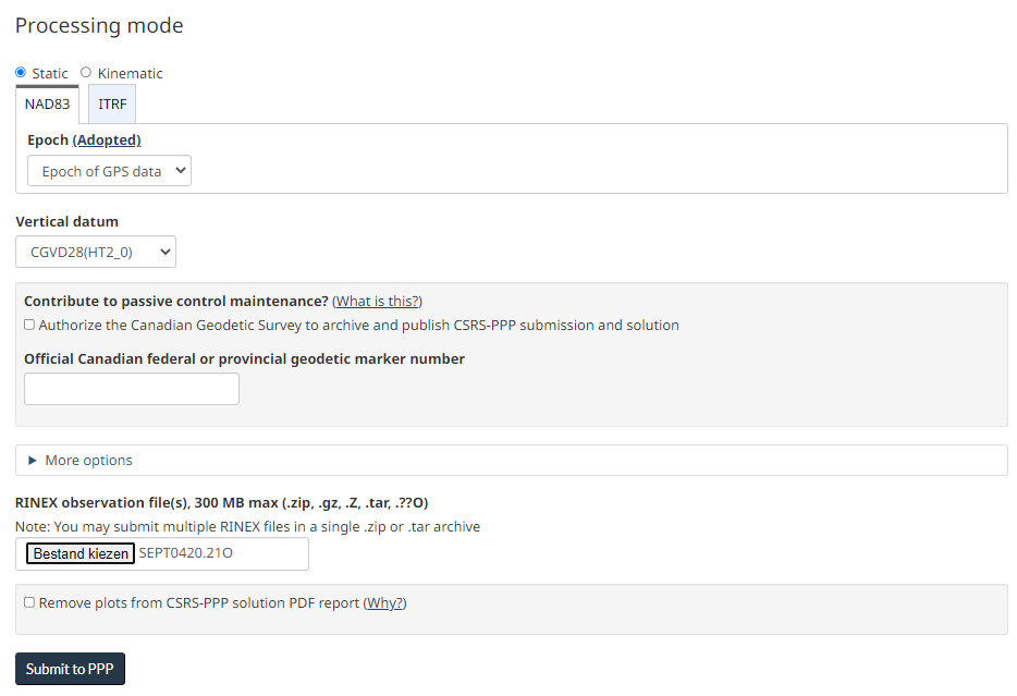
No marker on site? Record the base’s raw observations, then submit them to an online PPP service — CSRS-PPP at NRCan, OPUS, APPS. Expect to provide one to three hours of data as a minimum and 24 hours for the best solution, usually as RINEX; expect the answer a day later, occasionally two weeks. For drone work the delay is often acceptable, because the base log can be processed while the imagery is being stitched. A permanent base should always have a 24-hour PPP solution behind it.
The result is absolute: every rover position recorded against that base — this flight and every future one — refers to the PPP service’s absolute frame.
Average an RTK fix while the crew is still on site
With a reachable RTK service or another base, and no marker and no time to wait, the ground receiver can determine its own coordinate from RTK. Switch it into RTK Rover mode, let it compute fixed solutions against the service, log them, and average. The receiver needs the RTK Rover capability for this. Positions arrive in the PVTGeodetic and PVTCartesian SBF blocks, convert to ASCII with SBF Converter, and average in Excel, R or Python in minutes. The averaged coordinate is expressed in the service’s datum, which may not be the frame the deliverable requires.
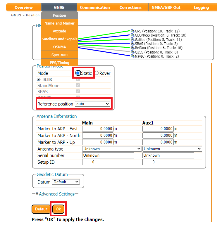
Auto — for bench tests, not for client data
Auto takes the first position the receiver believes is valid and refers everything to it. That position might be standalone, SBAS, PPP or RTK depending on the moment it was captured.
Relative accuracy across the flight is fine. What breaks is comparability — with another base, with last month’s flight, with the client’s existing survey — because the base has no accurate place in any frame. Auto also recomputes on every restart, so the same site produces a different coordinate tomorrow. Use it to check that a link works; do not use it to deliver data.
Converting a relative base position to an absolute one afterwards is possible: recompute the base position, for instance from RINEX of a local reference network with post-processing software such as Septentrio’s PPSDK, then reprocess every rover observation against the new base coordinate. It works, but it means reprocessing all flight data — which is exactly the cost that choosing a proper reference position up front avoids.
The correction stream to the autopilot
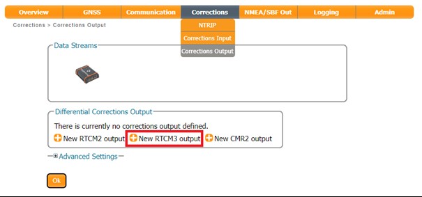
Creating the stream is a two-minute job in the receiver’s web interface: Corrections > Corrections output > New RTCMvX output, then pick the connection type. Serial to a telemetry radio is the classic drone setup; Ethernet, NTRIP and the internal caster follow the same pattern.
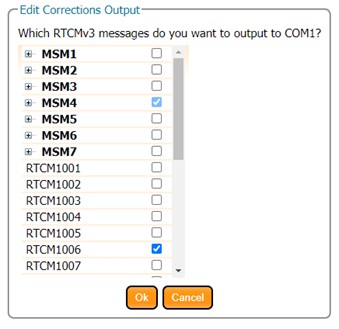
Choose RTCMv3. RTCMv2 is a fixed-length legacy format: bulkier on the air, no BeiDou or Galileo corrections, and missing many modern message types. CMR, CMR+ and CMR2 are Trimble’s proprietary formats with partly unpublished message definitions, so a third-party autopilot or receiver cannot be guaranteed to interpret every message.
On current Septentrio hardware, selecting RTCMv3 messages offers MSM4 for all four constellations plus the station-description messages a rover needs to interpret the corrections:
| Message | What it carries |
|---|---|
| RTCM1074 | GPS MSM4 |
| RTCM1084 | GLONASS MSM4 |
| RTCM1094 | Galileo MSM4 |
| RTCM1124 | BeiDou MSM4 |
| RTCM1006 | Station description — ARP and antenna height |
| RTCM1033 | Receiver and antenna description |
| RTCM1230 | GLONASS L1/L2 code-phase biases |
Older receivers default to the legacy set instead — 1004, 1006, 1012, 1033 and 1230 — which covers GPS and GLONASS L1/L2 only. Switching to MSM4 by hand, and adding 1006, 1033 and 1230 as general messages, is worth doing; the firmware reference manual for the specific model documents the details.
| Message | What it carries |
|---|---|
| RTCM1004 | Extended GPS observations, L1/L2 |
| RTCM1006 | Station description — ARP and antenna height |
| RTCM1012 | Extended GLONASS observations, L1/L2 |
| RTCM1033 | Receiver and antenna description |
| RTCM1230 | GLONASS L1/L2 code-phase biases |
Run the stream at 1 Hz. That is the rate real-time corrections are designed for, and changing it requires GNSS knowledge that is rarely worth acquiring for one site. Bandwidth is the reason to care: a richer message set at a faster rate needs a fatter link, and a telemetry radio is a thin link. Size the stream first, then confirm the radio carries it with margin.
Same tripod, three reference positions, three different maps
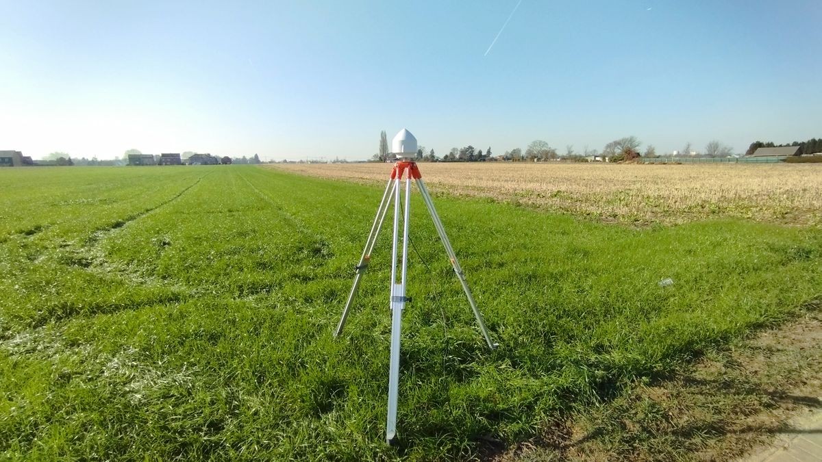
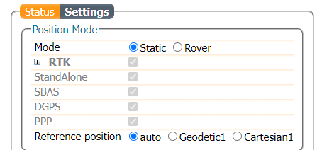
Septentrio’s example isolates the variable that matters. One PolaRx5e and one VeraPhase 6000, in open sky, are given three reference positions for the same physical location: a PPP solution computed from six hours of Support SBF data (24 hours recommended for best results), an average of six hours of RTK fixed positions with the receiver temporarily run as an RTK rover, and auto. Each configuration is written to the receiver, which is set to static mode and streams RTCM; a rover records positions against each in turn.
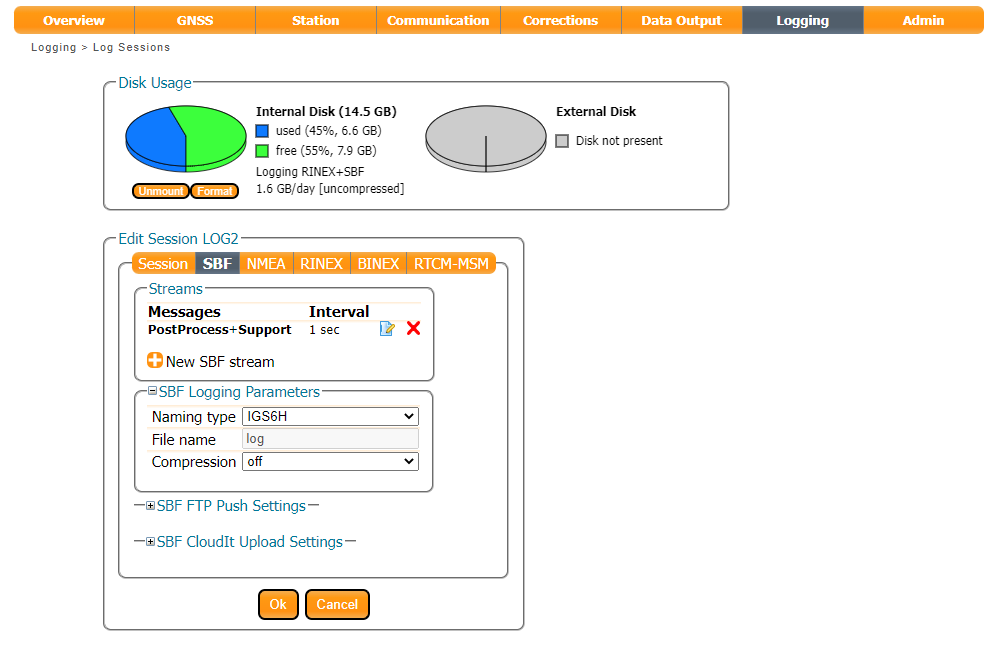
For the PPP run, logging uses the predefined Support SBF block group — everything needed to convert to RINEX — with the IGS6H naming convention so the whole session lands in one file. The PolaRx5e can also log RINEX directly.
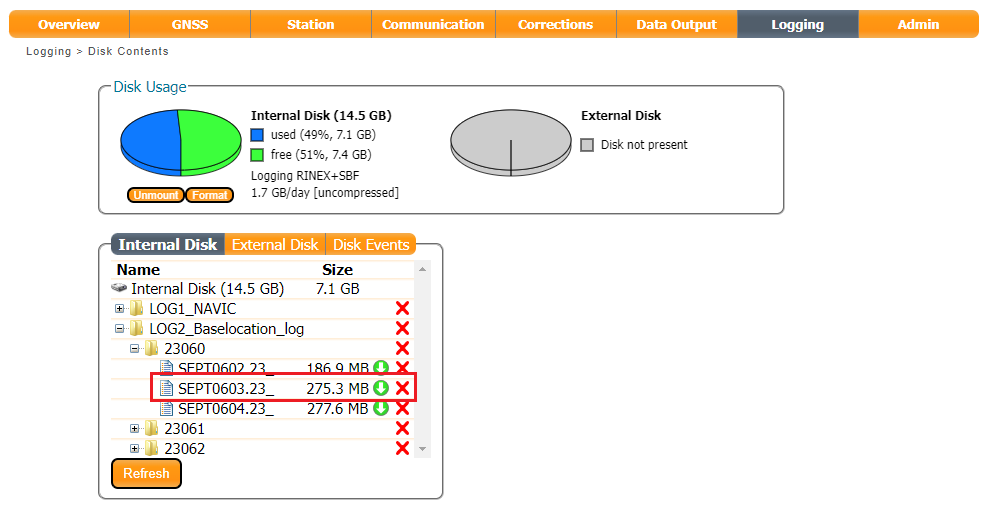
Six hours were recorded against a one-hour minimum, then downloaded, converted with SBF Converter and submitted.
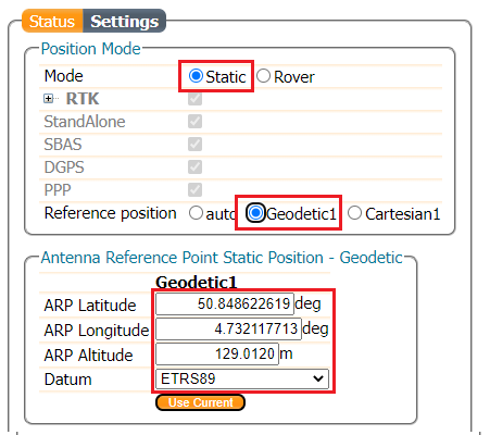
The PPP service returned the coordinate the next day — latitude 50.84862262, longitude 4.732126167, ellipsoidal height 129.012 — which was typed back into the receiver along with the RTCMv3 output and saved to boot.
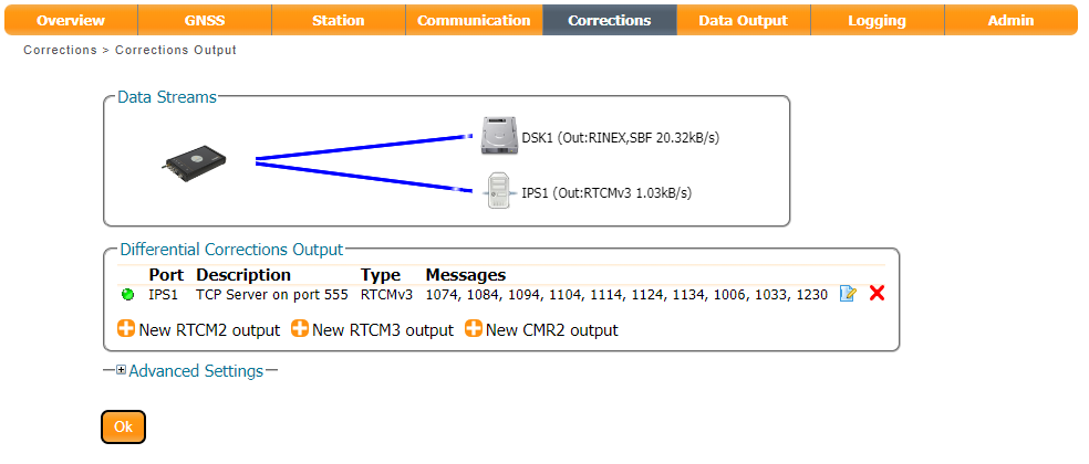

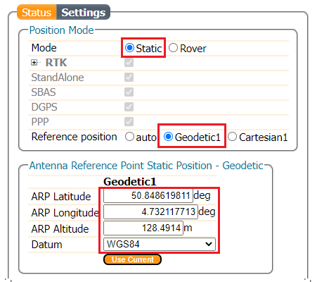
The RTK-averaged run used the same antenna and a fresh six-hour session, extracting fixed positions from PVTGeodetic and averaging them: latitude 50.84861981, longitude 4.732117713, ellipsoidal height 128.4914. The auto run simply set static mode with the static position on auto.
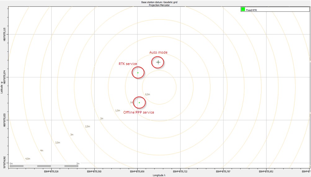
Plotting the three rover datasets together shows the whole argument in one image. RTK quality is excellent in every set — the aircraft would report a solid fix in all three cases — yet the three answers sit in different places, because the base coordinates differ.
The lower-left group belongs to the PPP-derived base: absolute WGS84 coordinates, comparable with any other WGS84 dataset. The upper-left group comes from the RTK-averaged base: also absolute, but in ETRS89, so comparable with other ETRS89 data rather than with WGS84 without transformation. The upper-right group is auto: nominally WGS84, but carrying an unknown offset, so only comparable with data computed from that same base.
For a drone programme the mapping is direct. Two flights over adjacent sites, each with its own auto base, will not register to each other. The same two flights with PPP or averaged-RTK bases will — provided both bases used the same datum.
Pre-flight checklist for the ground station
- Licence: RTK Base enabled on the ground receiver; RTK Rover enabled if the base coordinate will be averaged on site.
- Signals: the base produces corrections for every constellation and frequency the aircraft uses.
- Antenna: correct model selected in the receiver, calibration available, vertical, clear of reflectors, clear of transmitters and generators.
- Height: marker-to-ARP offset entered if the antenna stands over a control point.
- Reference position: marker, PPP or averaged RTK — and written down, with the epoch and datum, in the flight log.
- Output: RTCMv3 MSM4 including 1006, 1033 and 1230, at 1 Hz, fitted to the radio link’s bandwidth.
- Persistence: configuration saved to boot, so a battery swap does not silently reset it.
- Logging: raw data recorded on the base as well, so PPK stays available if the link drops mid-mission.
Questions drone crews ask
Do I still need a base station if I use an NTRIP service?
Only if you want control over the frame. A network RTK service removes the ground hardware and the tripod, but the absolute position of your map is then tied to that service’s reference stations and datum, and coverage and link quality become someone else’s problem. A local base keeps both under your control — which is why mapping crews often run a base for the flight and use the network as a fallback.
How far can the base be from the drone?
There is no single number, because the limit is set by how much ionospheric activity the baseline has to absorb, not by the receiver. Keep the base near the working area, and split large sites across several base positions instead of stretching one link.
Can one base serve both RTK during the flight and PPK afterwards?
Yes, and it should. Log raw observations on the base alongside the correction stream: if the radio link fails or the corrections arrive too late for a fixed solution, the same session supports post-processed kinematic work after landing.
Why do two flights over the same site not align?
Almost always different reference positions. If either base coordinate came from auto, or from a tripod that was re-set without measuring its height, the two datasets sit in different frames. Check what each flight’s base coordinate was — epoch, method and datum — before reprocessing anything.
Is a choke-ring antenna worth carrying to a drone site?
For temporary work, usually not. It is the best-performing static antenna and normally has an absolute calibration, but it is bulky. A geodetic antenna is adequate for a flight base; keep the choke ring for permanent installations and monitoring sites.
What does auto actually cost me?
Comparability, not accuracy. Each flight’s relative geometry is fine; what disappears is the ability to compare that flight with another base, another campaign or the client’s existing survey — and the position changes again after every restart.
Receivers for a drone base station
The ground side does not need a survey-grade monument, but it does need a receiver with RTK Base output and a correction link the aircraft can use. The HB6 box receiver and the EV322 both run Septentrio modules with the correction capabilities this workflow assumes, and log raw data for PPK; the HB10 and HB51 cover the airframe side where heading is also needed. The full line-up is on the base receiver page.
If you are setting up a base for a drone survey programme, tell us the aircraft, the autopilot and the site size, and we will match a receiver and antenna to it — including whether to run your own base or lean on a network service.
Talk to an engineer. Ask about a drone base station setup — or see the technical papers and research for the field data behind these recommendations.
Source
Septentrio Customer Support, How to set up a base station, chapters 1–6 — customersupport.septentrio.com. Figures and the coordinate values quoted above are reproduced from that document.