
The Short Answer
GNSS timing for drones gets a fraction of the attention that GNSS positioning gets, and that asymmetry is where the risk hides. Interference can leave a UAV holding a flawless centimetre fix while the time inside the log quietly moves. On an aircraft, time is not a bonus output: it stamps every geotag, drives event markers and camera triggers, and ties the GNSS solution to the IMU, LiDAR and flight-controller data. The mechanism behind the drift is specific — the delay through an antenna and receiver front end varies with frequency, so when interference pushes a receiver onto a different set of signals, the 1PPS position steps along with it. In-band zero-delay anti-jamming removes the step by cleaning the jammed band where it sits rather than switching away from it. In an urban jammer-gun test on mosaic hardware, every RTK Fix stayed inside 1 cm and every position inside 2 m while the jammer was transmitting — and the PPS never moved.
Specifying GNSS timing for a UAV platform? Send us the airframe, mission profile and the timing tolerance your payload needs, and we will match a receiver to it — Request a quote, or see the anti-jamming receiver range.
Why an aircraft should care about GNSS time at all
Most drone GNSS conversations start and end with position: how many centimetres, how fast to a fix, how many satellites. Time is treated as an implementation detail. In practice the opposite is true for anything that is processed after landing, because the position stream can only be as good as the time base it is attached to.
| What runs on GNSS time | How a drift shows up |
|---|---|
| PPK / post-processed trajectories | Base and rover time tags stop lining up cleanly; residuals smear instead of converging |
| Camera and LiDAR geotagging | Every frame inherits the offset, so the whole deliverable shifts together |
| Event markers and payload triggers | Trigger timing error — the frame is captured slightly late or early in the trajectory |
| GNSS / IMU fusion | The filter is fed a time base that is not what it thinks it is |
| Multi-aircraft operations | Two clocks that disagree produce two slightly different worlds |
| Post-flight incident review | Logs correlate poorly with what actually happened, exactly when you need them most |
None of these announce themselves in flight. That is the point: the operator sees a healthy fix, and the timing offset only surfaces later, in processing or in a discrepancy nobody can explain.
Two ways interference reaches a drone
Jamming floods the GNSS bands with RF noise so the satellite signals are buried. Spoofing transmits fake GNSS-like signals designed to be accepted instead of the real ones. The usual assumption is that jamming at least fails loudly — you see the signals go away — while spoofing is the subtle one. That assumption is only half right.
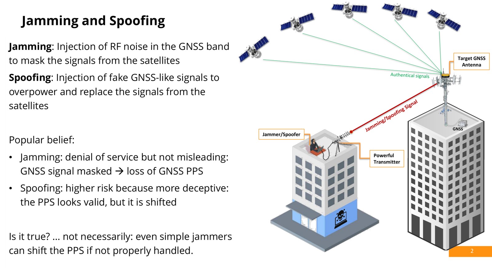
Image courtesy of Septentrio
The visible half of jamming is straightforward: carrier-to-noise density drops across the affected bands, and at sufficient power the receiver stops tracking those satellites altogether.
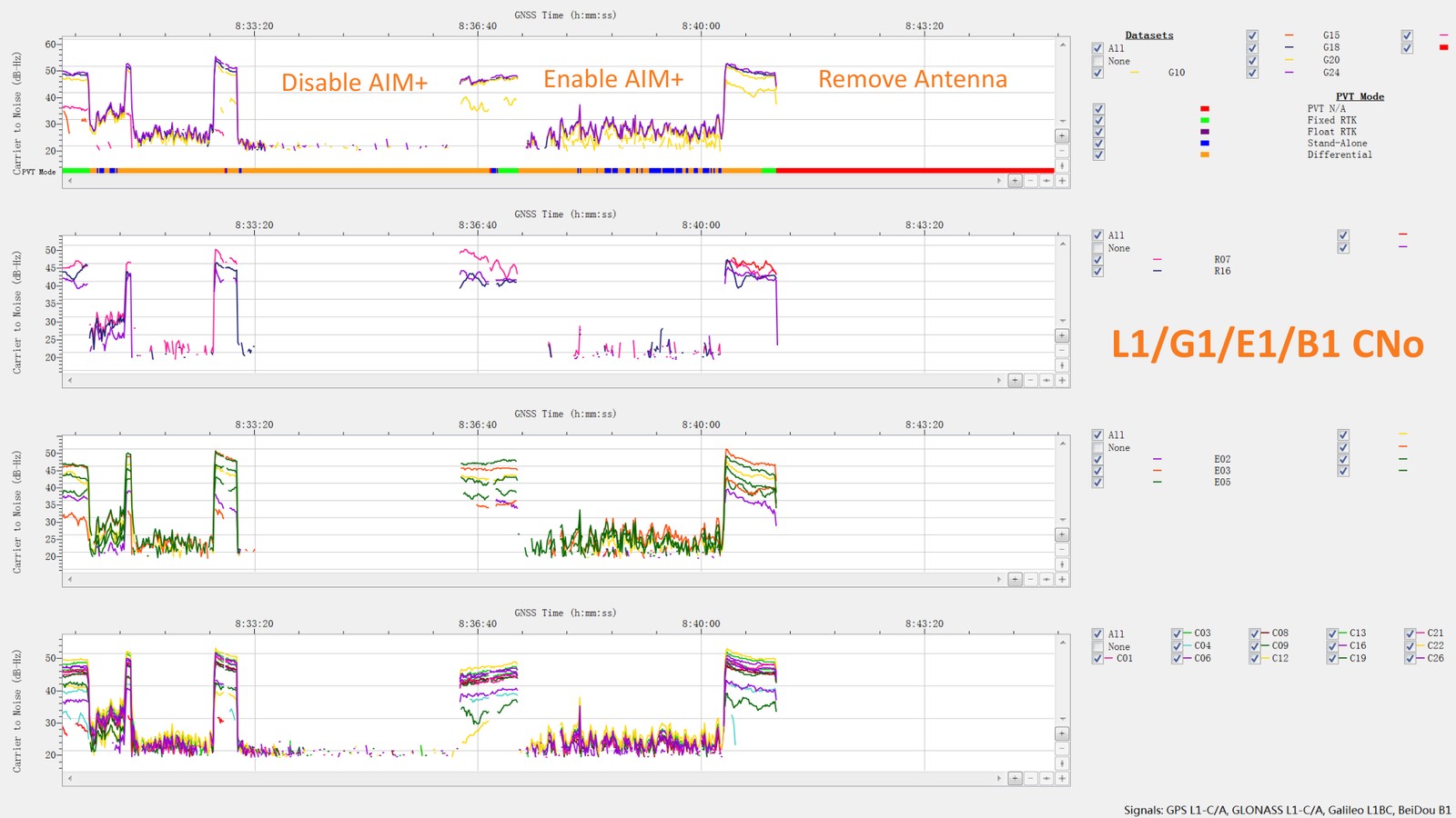
Image courtesy of Septentrio
The half of jamming that never says anything
Timing behaves nothing like tracking. A receiver under interference can keep emitting a PPS pulse with no interruption, and its own quality indicators will report the pulse as precise — because precision and correctness are different things. What changes is where the pulse sits in absolute time.
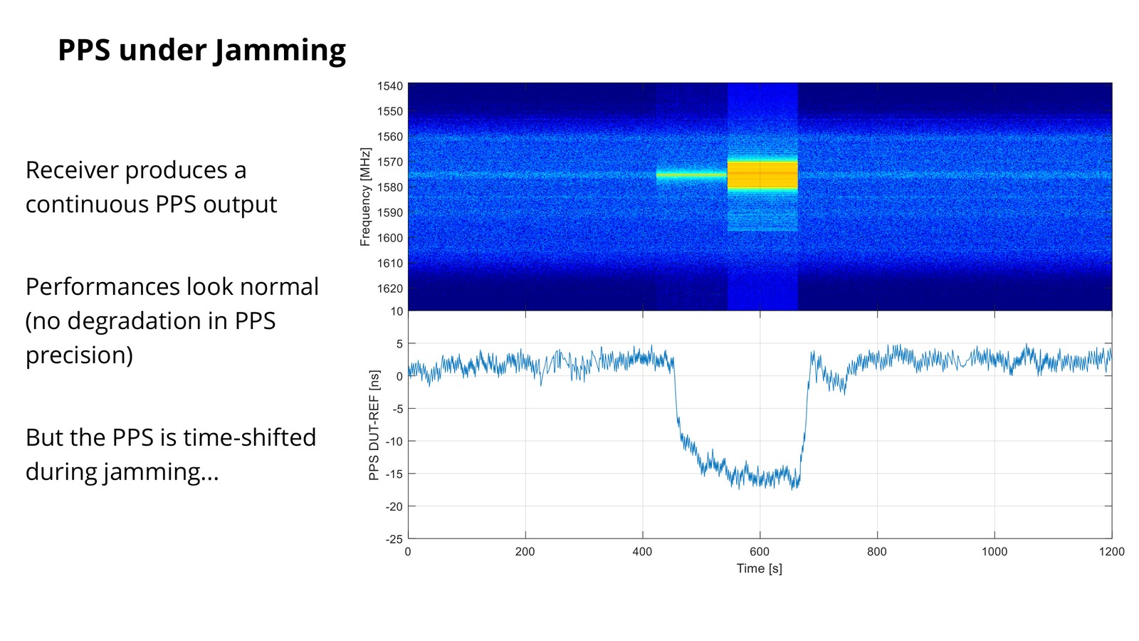
Image courtesy of Septentrio
Where the offset comes from
A multi-frequency receiver does not live on one signal. It builds its solution from signals drawn across several bands, which is what makes it robust under normal conditions. Every analog stage in the path — the antenna filter, the amplifier, the front end — delays those frequencies by slightly different amounts.
So when interference forces part of that signal set out of the picture, the composite delay through the receiver changes. A change in delay is a change in when the second is declared. Position absorbs this quietly; time does not.
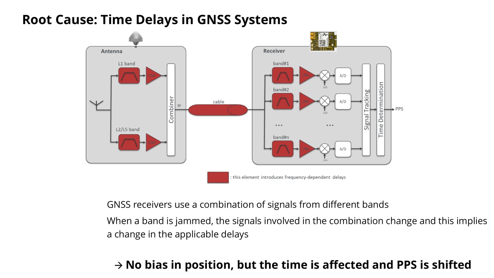
Image courtesy of Septentrio
Cleaning the band instead of leaving it
The classic anti-jam reflex is to detect interference and move to another set of signals. It protects the position solution, and it hands the timing solution a delay step every time it happens. Septentrio’s approach inverts the reflex: hold every band open, and clean the one being attacked.
- Calibrate in real time, in an interference-free environment;
- Do not switch between signal sets when interference appears;
- Clean the affected band in place — in-band zero-delay anti-jamming;
- Restrict the design to constant-delay filters and compensate for that delay;
- Use linear-phase filters, so the delay is deterministic by construction.
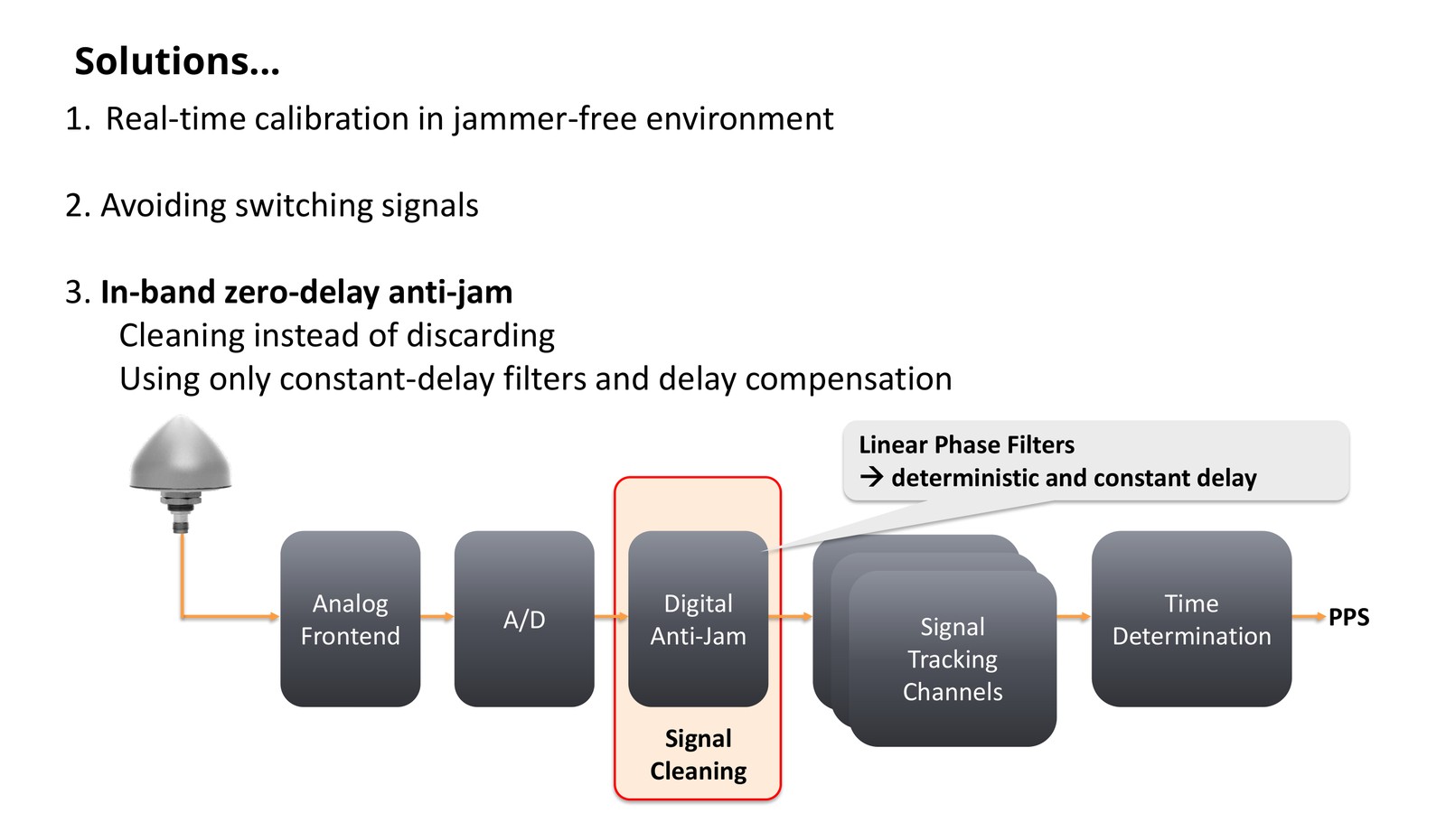
Image courtesy of Septentrio
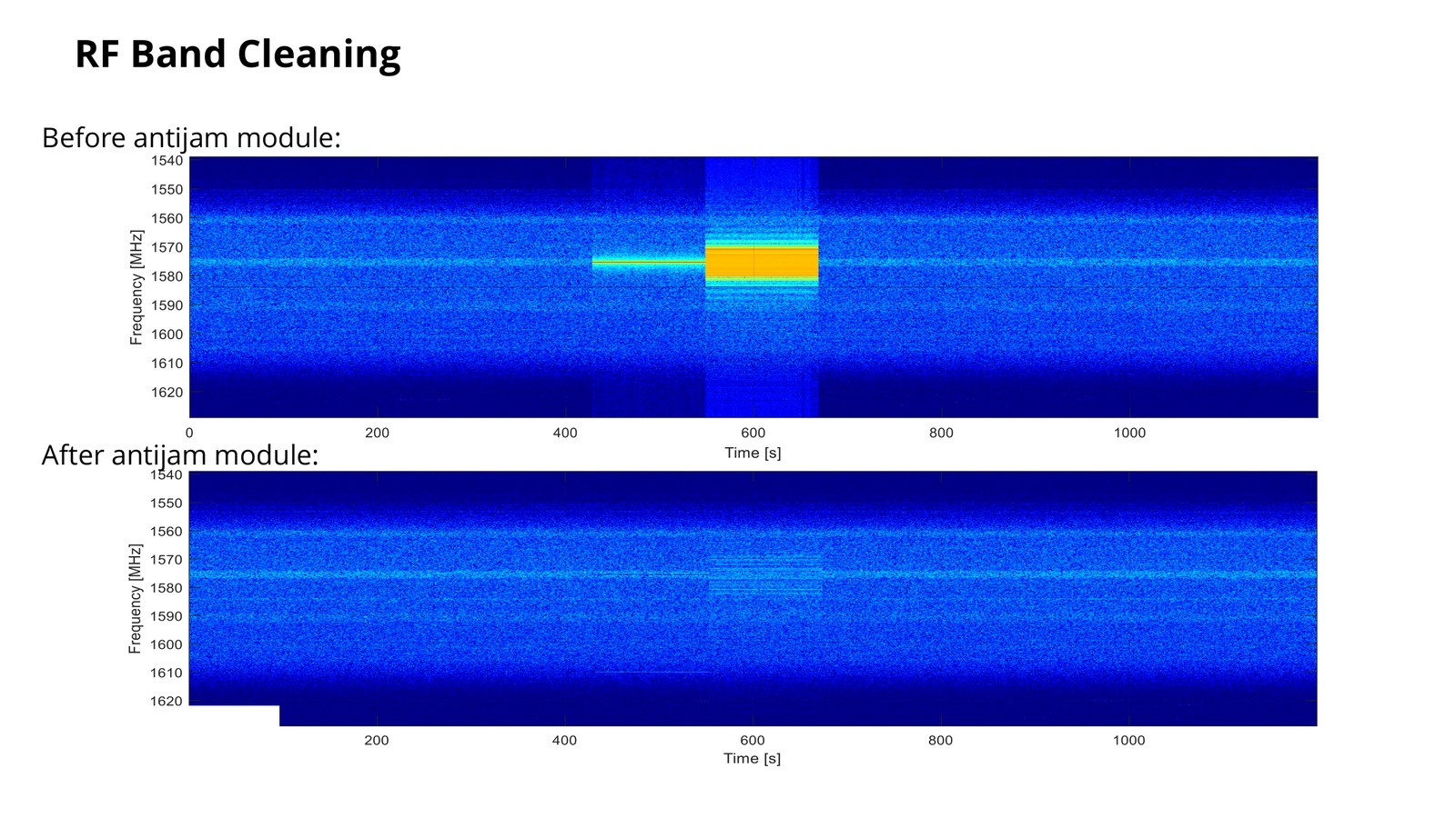
Image courtesy of Septentrio
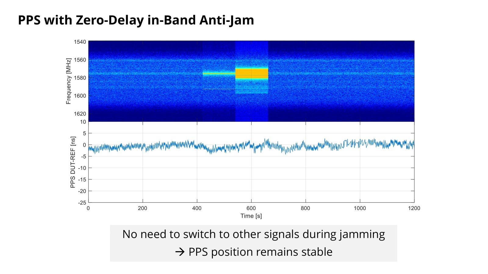
Image courtesy of Septentrio
| Switching to a clean signal set | Cleaning the jammed band | |
|---|---|---|
| Effect on position | Protected — the solution continues on other signals | Protected — the jammed band is returned to use |
| Effect on delay | Changes at the moment of switching | Unchanged; compensated and calibrated |
| Effect on PPS | Possible offset that no indicator reports | Stable position in time |
| What the log shows | That a re-selection happened | Interference detected and suppressed, band by band |
What it looked like in a city, with a jammer gun
This is not a bench simulation. A DJI GNSS jammer gun was aimed at mosaic (mini) hardware — a module class used in unmanned platforms — from the opposite side of a road in a city centre, while the receiver logged continuously to an internal TF card.
- Device under test: mosaic mini
- Antenna: Novatel full-band antenna
- Setting: downtown, close to the DJI office
- Interference source: DJI GNSS jammer gun
- Separation: 5–8 m, across the street
- Logging: internal TF card, continuous
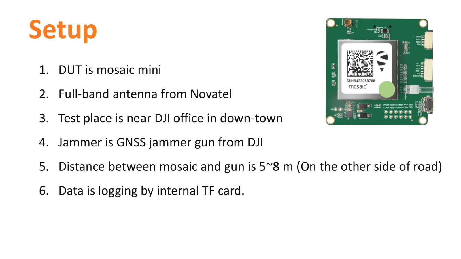
Image courtesy of Septentrio
Spectrum: jammer on, then mitigated
With the jammer transmitting, the L1 band carries three pronounced interference peaks — roughly 1563, 1575 and 1602 MHz. Switch AIM+ on and they disappear, leaving the noise floor behind.
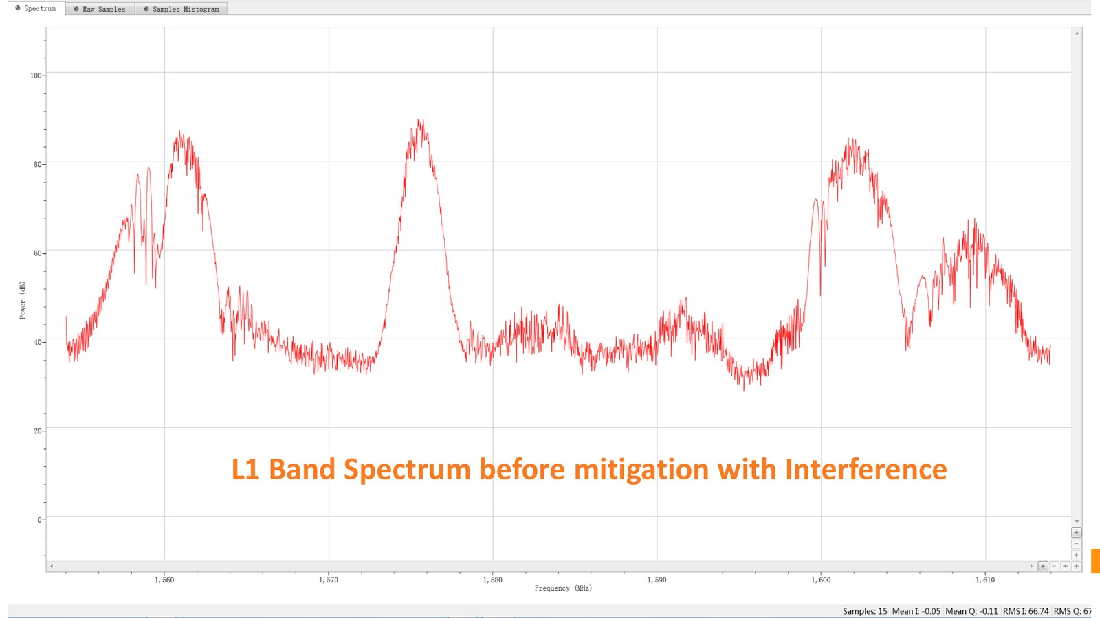
Image courtesy of Septentrio
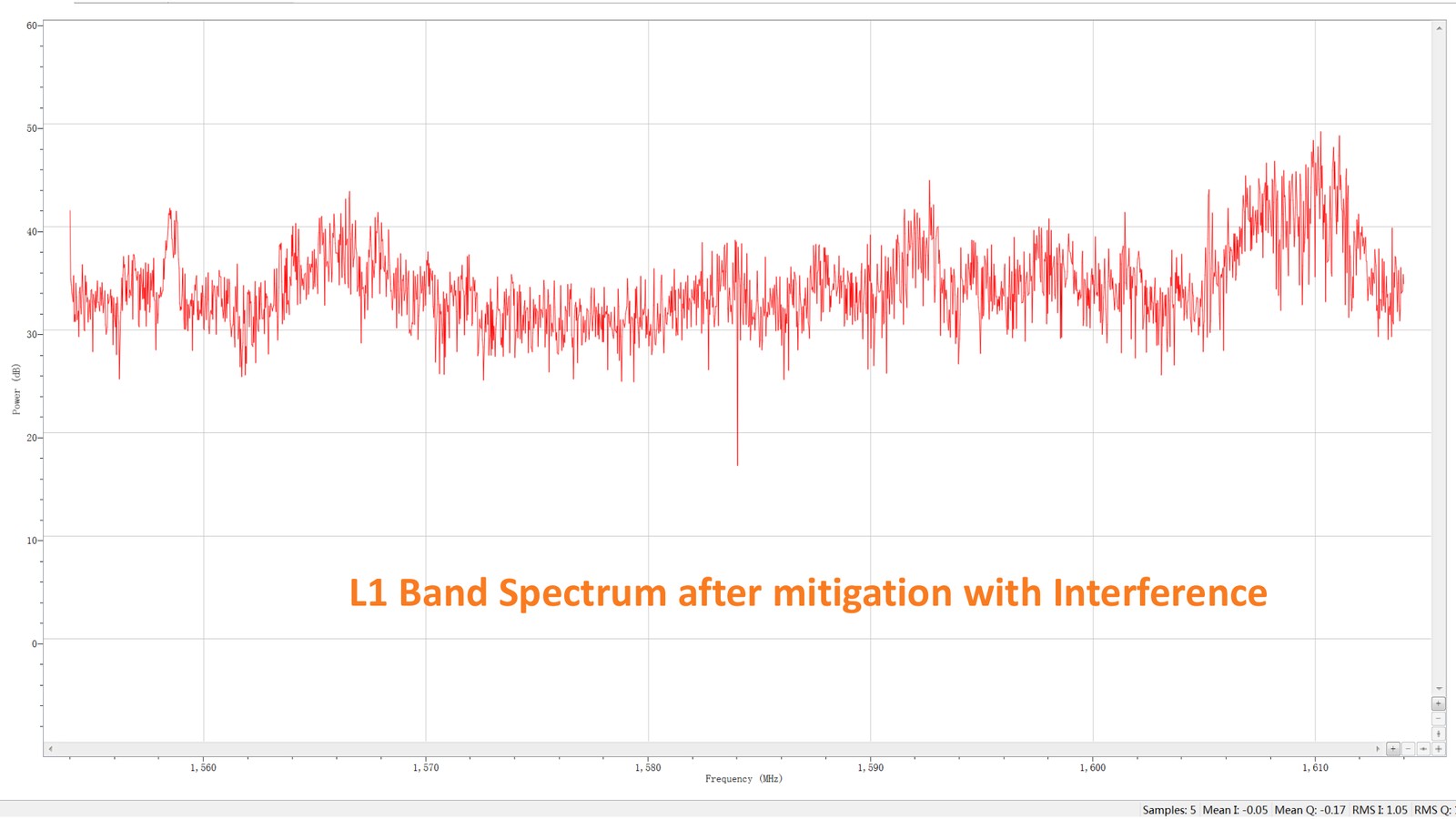
Image courtesy of Septentrio
What the receiver recorded about the interference
The receiver reports, per band, whether interference was detected and whether it was actually suppressed — status 8 for detected but unmitigated, status 2 for detected and mitigated. For a UAV operation that is post-flight evidence: the log tells you what the RF environment was doing during the flight, in the same file as the trajectory.
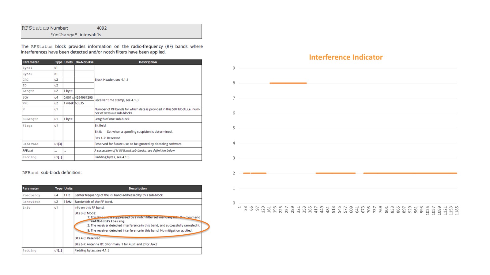
Image courtesy of Septentrio
Position, tracking and velocity through the event
In an urban canyon with an active jammer, all positions sat within 2 m, all RTK Fix positions within 1 cm, and the satellite count, the satellites contributing to the PVT solution and the velocity solution all stayed steady.
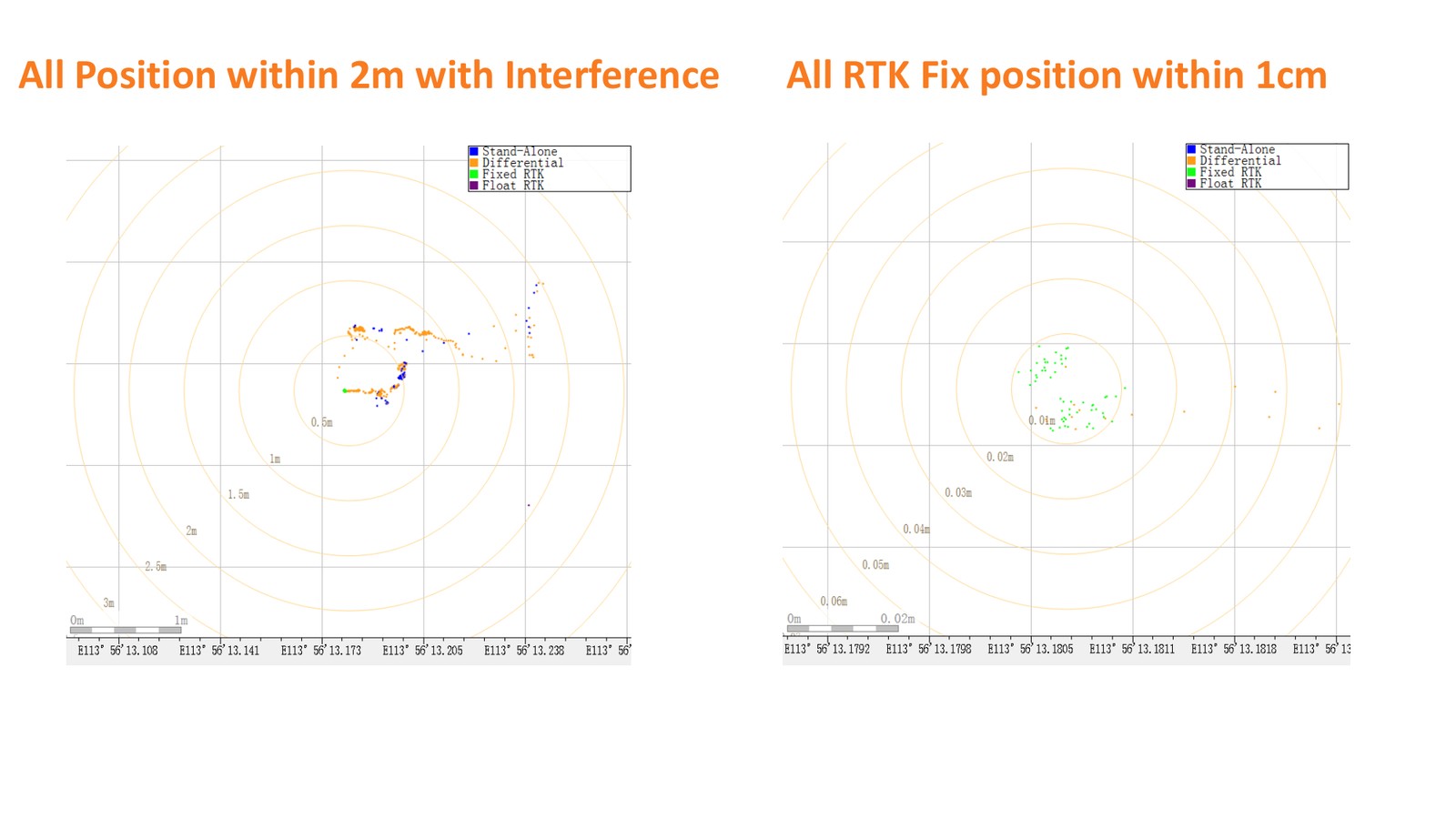
Image courtesy of Septentrio
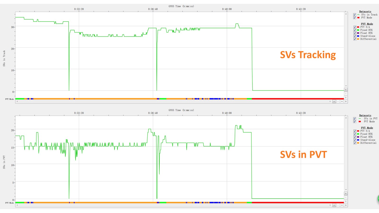
Image courtesy of Septentrio
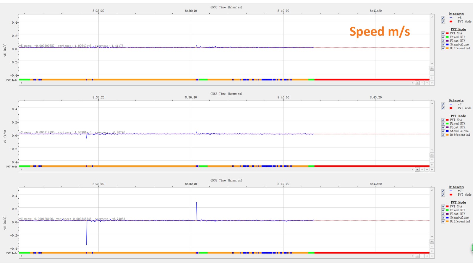
Image courtesy of Septentrio
Spec checklist for a UAV GNSS receiver
If timing inside the log has to survive interference, ask for these explicitly rather than assuming them from a general “anti-jamming” claim.
| Ask for | Why it matters on an aircraft |
|---|---|
| Interference mitigation that cleans in band instead of switching signal sets | No delay step, so the 1PPS cannot jump mid-mission |
| Published xPPS and event-marker accuracy | 5 ns and <20 ns on HB56-class hardware — the numbers your geotags inherit |
| Per-band interference status in the log | Turns an unexplained post-flight discrepancy into a documented RF event |
| Integrity monitoring on the measurements | Keeps inconsistent measurements out of the solution that feeds the timing |
| Anti-spoofing authentication (OSNMA) | Covers the attack that aims at the reference itself |
| Update rate that matches the payload | 100 Hz output keeps fast gimbals, LiDAR and trigger logic fed |
The receivers behind it: HB56, and the compact options
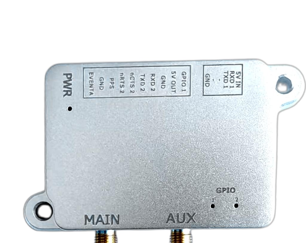
Everything described here ships as receiver behaviour, not as a service. The Eview HB56 carries a Septentrio mosaic-X5 core with AIM+ anti-jamming and anti-spoofing, IONO+, APME+ multipath mitigation, LOCE+ and RAIM+ integrity monitoring, a 100 Hz update rate, xPPS output specified at 5 ns and event accuracy below 20 ns — in a 60 g, 7.6 × 6.9 × 1.3 cm package for platforms that can carry a full multi-frequency receiver.
Smaller airframes usually need a different trade: the HBEV322 / HBEV322H compact RTK GNSS receiver on a Septentrio mosaic-G5 P3H engine, the HB52H / HB52 ultralight RTK module, and, where attitude is needed as well as position, the HB10 dual-antenna receiver on AsteRx-m3 Pro+. All of them carry Septentrio Inside, and the integration questions are the same: which bands matter at your site, what your payload triggers on, and how much timing tolerance the deliverable can absorb.
FAQ: drone GNSS timing under interference
Can interference really move my timestamps if the fix looks perfect?
Yes. Tracking and timing degrade differently. C/N0 loss shows up in the fix quality, but a timing offset can exist while the receiver still reports a fixed solution and a precise-looking PPS.
How would I notice a timing offset after a flight?
Indirectly: PPK residuals that will not converge cleanly, geotagged frames that sit consistently off the trajectory, or event-marker timing that does not match the commanded trigger. Interference status in the log tells you whether the RF environment is a candidate explanation.
Does the aircraft lose the fix when this happens?
Not necessarily. In the urban jammer-gun test the RTK Fix held within 1 cm and the position within 2 m. Losing the fix is the loud failure; the quiet one is keeping it while the clock moves.
Is this only relevant to large platforms?
No. The test hardware was a mosaic mini, a small-form-factor module. What scales with airframe size is payload power and mass budget, not whether the timing problem exists.
Does in-band cleaning replace RAIM+ or anti-spoofing?
No — they cover different failures. Anti-jamming protects the RF environment, RAIM+ screens the measurements so a bad one cannot bias the solution, and OSNMA authentication covers a spoofed reference. A resilient platform wants all three.
Next step
Tell us the airframe, the mission profile and what your downstream processing does with time — we will come back with a receiver configuration and a price. Request a quote, or contact the team. For the interference side of the problem in the field, read how to find and suppress drone GNSS interference and the Jammertest 2025 results with AIM+ on UAVs.
Sources: Septentrio, ITSF 2025 Prague — “Stable GNSS Timing Under Jamming Attacks: Introducing Zero-Delay Anti-Jam Technology” (Jean-Marie Sleewaegen, Wim De Wilde, Samuel Heijmink), including the urban jammer-gun test on mosaic hardware. Receiver specifications from the Eview HB50/HB56 datasheet and Eview product documentation.