

Most drone GNSS problems blamed on “bad satellites” are local RF interference. The receiver already contains the tool to prove it: a spectrum view that plots the live RF environment, three configurable notch filters for narrowband sources, and a Wideband Interference Mitigation switch for wideband and pulsed interference. Here is how to work the problem in the field instead of guessing.
Losing RTK on site? Send us the spectrum capture and the flight log and we will help you read it — Request a quote or see the anti-jamming receiver range.
What Interference Looks Like From the Air
The GNSS signal reaching the antenna is extremely weak, so it is easily overpowered by other radio traffic on the same frequencies — and the effect is usually worst in the GLONASS L2 and L5 bands. On a UAV that surfaces as a specific set of symptoms: RTK that will not initialise on the pad, a fix that drops only over one part of the site, or a solution that drifts while still reporting as fixed.
Some of it is accidental, from equipment near the launch point. Some is deliberate: illegal jammers can take out GPS receivers within roughly a 100-metre radius, and toll-evasion jammers fitted to trucks knock out nearby GPS equipment as collateral. Spoofing is the third case — false position information transmitted so the receiver reports a position that is simply wrong.
Field Step 1: Capture a Baseline Spectrum
Before flying, open the receiver’s spectrum window and record what “clean” looks like at that location. The plot is computed from baseband samples at the ADC output, so it reflects the real RF environment at your antenna — no external analyser required. Use Show table to read band-by-band signal strength.
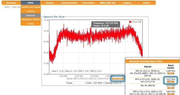
Image courtesy of @Septentrio
Figure 1 is the L2 band with GPS L2P marked at 1227.60 MHz. Capturing this before the mission, then again at the moment of failure, turns a vague “GNSS was bad today” report into a comparison.
Field Step 2: Notch Filter Anything Narrowband
Nearby electronics can put narrowband energy into part of the GNSS spectrum. Three notch filters handle it, each in automatic or manual mode, removing the narrowband slice of RF spectrum around the offender. The L2 band — open to amateur radio use — is the most common culprit.
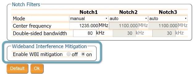
Image courtesy of @Septentrio
Leave the filters in automatic mode and the receiver manages the affected region itself. Switch to manual when you need to target a specific source: set the centre frequency and the bandwidth, as in Figure 4 where Notch 1 is 1235.000 MHz at 80 kHz double-sided bandwidth. Selecting OK applies the setting — so you can prove the cause live, on the pad, before committing to a flight.
Field Step 3: Turn On WBI for Wideband and Pulsed Sources
Wideband interference comes from ranging and communication equipment unintentionally, and from jamming devices intentionally. The Wideband Interference Mitigation system lowers the impact of both, and it handles pulsed interference better than the conventional pulse-blanking approach. It is one switch in the same dialog.
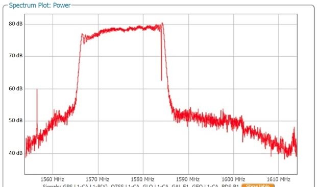
Image courtesy of @Septentrio
In Figure 5 the band shows a jammer’s output superimposed on the antenna signal. Figure 6 is the same conditions with WBI enabled, where the interference is significantly reduced. For a mission flown along a road corridor or a logistics yard, that single switch is often the difference between a usable RTK fix and none at all.
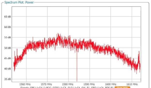
Image courtesy of @Septentrio
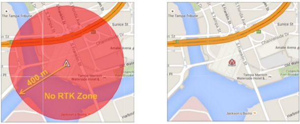
Image courtesy of @Septentrio
Symptom-to-Action Table
| Flight symptom | Probable cause | Action |
|---|---|---|
| RTK will not initialise at the launch point | Narrowband source on site, often L2 | Notch filter on the offending centre frequency |
| Fix drops along one corridor only | Wideband or deliberate jamming | Enable WBI; log spectrum at the failure point |
| Intermittent tracking breaks in bursts | Pulsed interference | Enable WBI rather than pulse blanking |
| Position offsets with no loss of signal | Spoofing | Mitigation plus measurement-level integrity checks |
Turning This Into a Receiver Requirement
Detection and cancellation reduce downtime and keep the aircraft flying safely, and because the spectrum is readable through the receiver’s output interface, the crew can identify the interference type and its likely direction instead of grounding for the day. What you want on the airframe is a receiver that shows you the spectrum, lets you notch what you find, and offers wideband mitigation as standard — our HB59 OEM receiver and HB10 dual-antenna receiver both run Septentrio Inside. Pair that with the SAT-count and RTK-fixed analysis workflow when a flight does not go to plan.
FAQ
How do I know it is interference rather than bad satellite geometry?
Look at the spectrum and the per-band signal strength. Geometry problems show healthy signals and poor dilution of precision; interference shows a raised or spiky RF floor, often confined to one band.
Do I need extra analysing equipment on site?
No. The receiver computes the spectrum from baseband samples at the ADC output, so the spectrum view and signal strength table are available from the receiver itself.
How many notch filters can I configure?
Three, each in automatic or manual mode. Manual mode takes a centre frequency and a double-sided bandwidth.
Will WBI help with a pulsed jammer?
Yes. WBI reduces pulsed interference more effectively than traditional pulse blanking, on top of its wideband capability.
Does interference mitigation cover spoofing too?
AIM+ provides protection against spoofing and cancels deliberate interference, but a spoofed signal cannot always be identified from the RF spectrum alone — pair it with integrity monitoring at the measurement level.
Send us your site, airframe and the interference you are seeing — request a quote and we will match the receiver to the environment.